MX100 PC-BASED DATA ACQUISITION UNIT
- MX100 Style S3 New!
- 30-ch input module
- Windows Vista compatible
- Alarm levels increased from 2 to 4
- Multi-Channel Capability, High Isolation Voltage
- Multi-Interval Measurement
- Flexible System Configuration
- Versatile PC-Based Software Options
- Easy Software Setup
- No Re-Wiring between Measurements
- All-in-one “Quick Start Packages” with 10, 20, or 30 Channels
Product Description
The table below provides reference information on the maximum number of measurable channels in relevant measurement intervals (when using Yokogawa’s proprietary software):
The relationship between measurement intervals and the number of channels largely depends on the performance of the PC. The actual performance may differ from that shown in the table.
<PC System Requirements>
CPU: Pentium 4 3.2 GHz; Memory: 1 GB; OS: Windows 2000; Hard disk: 160 GB
Communication interface: Ethernet 100Base-TX
Multi-Interval Measurement
Three types of measurement intervals can be used in a single system in various combinations. Measurement intervals are specified for each module. It is also possible to set different types of input modules to the same measurement interval or to set the same type of input modules to different measurement intervals. Twelve measurement intervals are available as userselectable options: 10 ms, 50 ms, 100 ms, 200 ms, 500 ms, 1 s, 2 s, 5 s, 10 s, 20 s, 30 s and 60 s. Please note, however, that measurement intervals of 10/50 ms cannot be set to the Medium-speed Universal Input Module (MX110-UNV-M10).
Examples of Setting Measurement Intervals
 | Multi-interval systems can be flexibly built for each module as shown in the figure below. Three colors |
Monitor Window Using Yokogawa’s Proprietary PC Software
 | The window shows measurement values by measurement intervals. Measurement can be performed while confirming rapidly-changing signals and slowly-changing signals simultaneously. |
A: Measurement of sine waves at 0.5 Hz with a measurement interval of 100 ms
B: Measurement of sine waves at 8 Hz with a measurement interval of 10 ms
C: Measurement of sine waves at 1 Hz with a measurement interval of 50 ms
High Withstand Voltage (Reinforced Insulation)
Reinforced (double) insulation has been provided between the input terminals and the case to achieve a high withstand voltage of 600 Vrms/VDC (continuous). As shown below, each battery voltage can be measured even if the batteries are stacked to increase common-mode voltages.

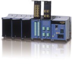
The main module is the engine that controls data acquisition. It is equipped with a power supply, an Ethernet port, and a CompactFlash card slot. One main module can accommodate up to six input/output modules. The user can choose up to six moduels of any type.
") Ethernet port: For communication with the PC. Automatic recognition of 100Base-TX or 10Base-TCF (CompactFlash) Card Slot: With the CF Card, measured data is saved to the card if communication with the PC is interrupted. Since the card provides data backup, you do not have to worry about the possible loss of data even if the MX is configured for PC-based measurement. | Data Backup Time by CF Card Size (Note: Minutes/hours/days are approximate.)
|
Input Modules

| Name | Model | Number of channels | Shortest measurement interval | Description |
| 30 ch general purpose input module with 500 ms scan speed | MX110-VTDL30 | 30 | 500 ms | Clamp terminal, DCV/TC/DI |
| MX110-VTDL30/H3 | 30 | 500 ms | M3 screw terminal, DCV/TC/DI |

| Name | Model | Number of channels | Shortest measurement interval | Description |
| Universal Input Modules | MX110-UNV-H04 | 4 | 10 ms | DC voltage, thermocouple, 3-wire RTD, DI (non-voltage contact, Level (5 V logic)). Mixed input allowed. |
| MX110-UNV-M10 | 10 | 100 ms | DC voltage, thermocouple, 3-wire RTD, DI (non-voltage contact, Level (5 V logic)). Mixed input allowed. | |
| 4-Wire RTD and Resistance Input Module | MX110-V4R-M06 | 6 | 100 ms | DC voltage, 4-wire RTD, 4-wire resistance, DI (non-voltage contact, Level (5 V logic)). Mixed input allowed. |
| Strain Input Modules | MX112-B12-M04 | 4 | 100 ms | Built-in bridge resistance of 120 ohm |
| MX112-B35-M04 | Built-in bridge resistance of 350 ohm | |||
| MX112-NDI-M04 | For connection with an external bridge head and strain gauge type sensor (NDIS connector)) | |||
| 5 V Digital Input Module | MX115-D05-H10 | 10 | 10 ms | Non-voltage contact, open collector, and Level (5 V logic). Mixed input allowed. |
| 24 V Digital Input Module | MX115-D24-H10 | 10 | 10 ms | Level (24 V logic), Vth = 12 V |
Output Modules
| Name | Model | Number of channels | Ouput update interval | Description |
| Analog Output Module | MX120-VAO-M08 | 8 | 100 ms | Allows mixed voltage (±10 V) and current (4-20 mA) output |
| PWM Output Module | MX120-PWM-M08 | 8 | 100 ms | Pulse width modulation output module |
| Digital Output Module | MX125-MKC-M10 | 10 | 100 ms | “A” contact (SPST) |
Base Plate
Base plates available for all configurations, from 1 to 6 input/output modules.
When used for the MW100/MX100, you must replace the attachment with the one that comes standard with the MW100/MX100.
Accessories
 | Connector Covers Connector covers for open slotsAC Adapter (772075) AC adapter for the DC power model. Operating temperature range: 0 to 40° *Only for the MW100 |
Accessories (Removable Terminal)
 | All input/output terminals are removable except for those of the MX112-NDI-M04. If multiple terminals are prepared ahead of time, no re-wiring is needed between measurements. |
")
| Model | Description |
| 772061 | Screw (M4) terminal block (RJC (reference junction compensation) included). For use in combination with 772062. Compatible with MX110-UNV-M10, MX115-D05-H10, and MX115-D24-H10. |
| 772062 | Connection cable between input modules and the screw terminal block. Compatible with MX110-UNV-M10, MX115-D05-H10, and MX115-D24-H10. |
| 772063 | Plate with clamp terminals (RJC included). Compatible with MX110-UNV-M10, MX115-D05-H10, and MX115-D24-H10. |
| 772064 | Clamp terminals. Compatible with MX110-UNV-H04. |
| 772065 | Clamp terminals. Compatible with MX120-VAO-M08, MX120-PWM-M08, and MX125-MKC-M10. |
| 772067 | Plate with clamp terminals. Compatible with MX110-V4R-M06. |
| 772068 | Plate with clamp terminals (Built-in bridge resistance of 120 ohm). Compatible with MX112-Bxx-M04. |
| 772069 | Plate with clamp terminals (Built-in bridge resistance of 350 ohm). Compatible with MX112-Bxx-M04. |
| 772080 | Plate with screw (M3) terminal (RJC included). Compatible with MX110-UNV-M10, MX115-D05-H10, and MX115-D24-H10. |
| 772081 | Plate with clamp terminal for current with 10 ohm built in bridge resistance, applies to MX110-UNV-M10 |
| 772082 | Plate with clamp terminal for current with 100 ohm built in bridge resistance, applies to MX110-UNV-M10 |
| 772083 | Plate with clamp terminal for current with 250 ohm built in bridge resistance, applies to MX110-UNV-M10 |
Datasheet